
Hose Master
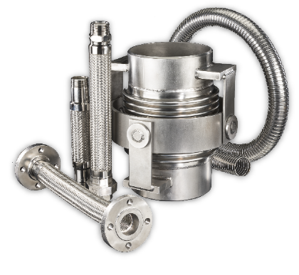
Innovative Flexible Metal Hose and Expansion Joint Solutions
Designed for Ultimate Reliability and Peak Performance in Even the Most Challenging Applications

Industry Spotlight: Data Centers
Hose Master is revolutionizing data center liquid cooling with advanced flexible metal solutions engineered for maximized facility uptime.

Cutting-Edge Solutions for Your Industry
Empowering industries to solve, innovate, and excel with state-of-the-art flex metal hoses and expansion joints. See the benefits today.
-

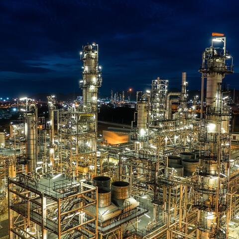
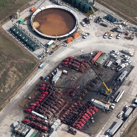
Refinery processes require hose assemblies for petroleum transfer, steam lines, and...
-
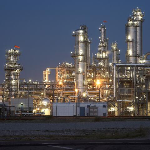
The Petrochemical industry has hose requirements similar to the ones found in refining...
-

Cryogenics applications spread across industries, from pharmaceutical manufacturing...
-
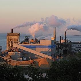
Pulp & Paper mills use a lot of steam and various chemicals in their manufacturing...
-

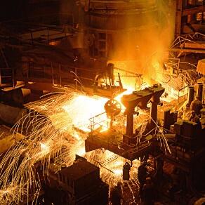
Utilities and power plants use metal hose and expansion joints for steam piping systems,...
-

PEI flex connectors are used to absorb vibration and accommodate misalignment or...
-
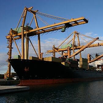
Typical metal hose applications in the Marine & Shipbuilding industry include expansion...
-
Because of its abrasion resistance and decreased loading times, metal hose is superior...
-
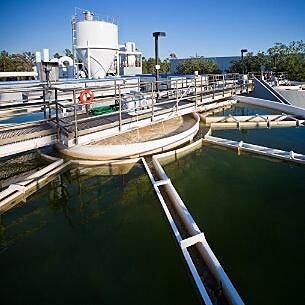
Water treatment facilities use chlorine in their purification process, and Hose Master’s...
-

The semiconductor industry demands high-performance hoses to handle corrosive etching...
-

The rapid growth in demand for data storage requires more sophisticated cooling systems...
-
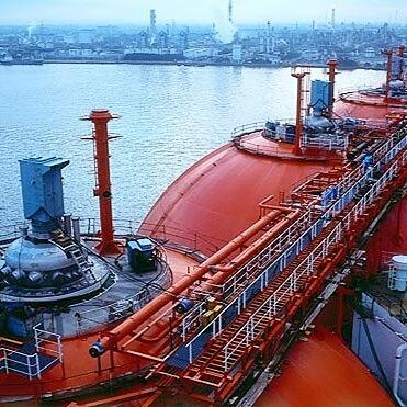
Liquefied Natural Gas/LNG transfer hoses must endure cryogenic temperatures (-260°...


Hose Master University
Hose Master University provides the most comprehensive training in Metal Hose, Expansion Joints and their applications.
- Metal Hose & Expansion Joints 101 & 201 Courses
- Value Selling
- Application Selling by Industry
- Webinar Courses
- On-Site and Field Training
Tools You Can Use
Resources to help select the right application and hose
Here you will find a vast collection of valuable resources, including helpful technical information, product & application literature, certifications, warranties, and terms & conditions. These resources, along with our blog and videos, are designed to help you get the information you need to solve your application challenges.

Check Out Our Newest Blog Posts and Videos
Discover valuable insights, indispensable tools, and expert guidance tailored to fuel your success on our blog, where we share our in-depth product knowledge and application expertise.


-
When to Use Flexible Metal Products
-
Select the Right Hose for Your Application
-
Select the Right Corrugated Metal Hose
-
Select the Right Stripwound Metal Hose